What Is a Cleanroom Chiller System?
A Cleanroom Chiller System is more than a cooling plant. It helps control temperature and humidity while supporting the airflow conditions that protect sensitive processes. In a semiconductor facility, for example, heat from process tools, pumps, and lighting can build up across tightly controlled rooms. Chilled water carries that heat away. The system must also respond steadily when equipment loads change, rather than simply deliver the coldest water possible.
The energy stakes are significant. Lawrence Berkeley National Laboratory cleanroom energy research has identified HVAC as a major cleanroom energy load, with reported shares around half of facility use in some settings. That figure is not universal; room classification, climate, operating hours, and equipment all matter. ISO 14644-1:2015 sets airborne-particle cleanliness classifications, while ASHRAE guidance addresses the engineering demands of clean spaces. Together, these references show why chiller selection cannot be separated from filtration, air changes, redundancy, and controls. Small control errors can mean unstable room conditions or avoidable energy use. A practical design also considers water quality, maintenance access, and what happens during a chiller outage. The details matter.
This guide explains what a Cleanroom Chiller System includes, how it works, and which design choices affect reliability and operating cost. It also questions a common assumption: bigger equipment is not automatically safer. Oversizing can create control problems. A balanced system, matched to real loads and verified with operating data, is usually the stronger starting point.
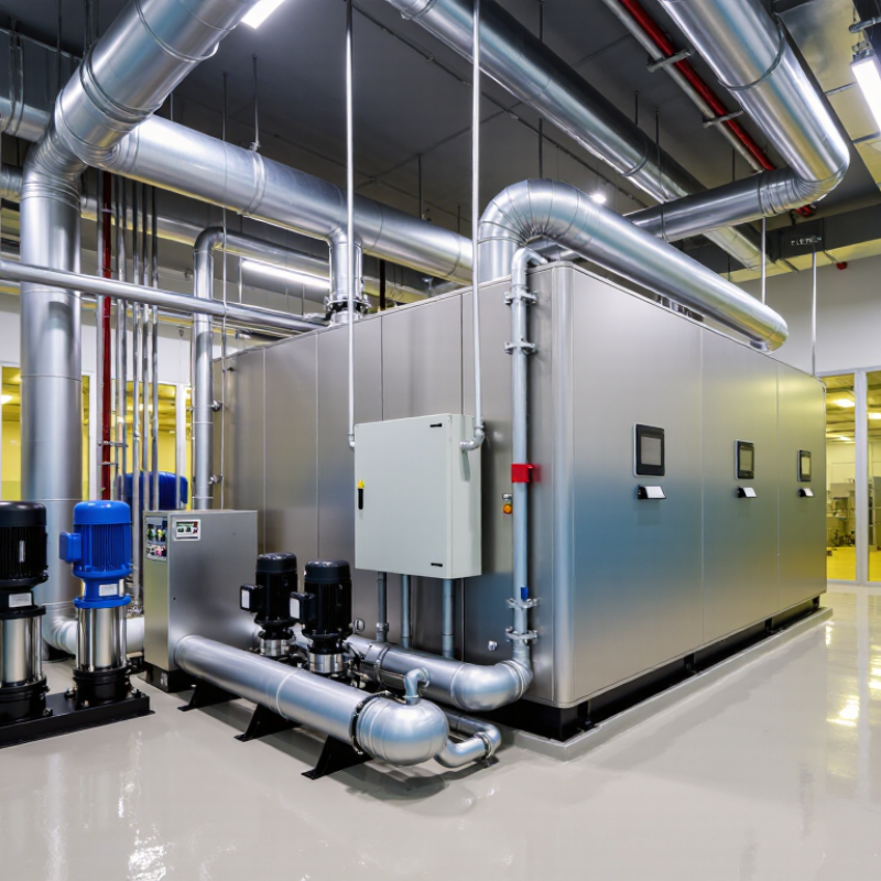
Definition and Purpose of a Cleanroom Chiller System
A cleanroom chiller system removes heat from chilled water and circulates it to air-handling coils or process equipment. Its purpose is to help maintain stable room temperatures and support humidity control, while equipment and manufacturing processes generate heat. It does not filter particles. That matters: filtration and carefully designed airflow handle particle control, while the chiller supports the environment those systems need.
ISO 14644-1:2015 classifies cleanrooms by airborne particle concentration. For ISO Class 5, the limit is 3,520 particles per cubic metre at 0.5 micrometres and larger. Chilled water helps cooling coils manage heat and moisture, but actual performance depends on airflow, filtration, and room loads. A chiller alone cannot guarantee a cleanroom classification.
Energy use also deserves attention. U.S. Department of Energy manufacturing guidance reports that cleanrooms can use 10 to 100 times more energy per floor area than typical offices. Stable water temperatures, appropriate load control, and preventive maintenance can help manage demand. For example, operators can compare supply and return-water temperatures during routine checks. A compromise remains: equipment sized for peak demand may run inefficiently during quieter shifts. It is worth reviewing real operating data.
| Aspect | Description | Purpose or design consideration |
|---|---|---|
| Definition | A cleanroom chiller system is a cooling system that removes heat from water or another circulating fluid and supplies chilled fluid to cooling equipment serving a cleanroom. | It provides a controlled source of cooling for the facility’s environmental-control and process systems. |
| Typical cooling path | The chiller cools circulating water. Pumps deliver it through piping to cooling coils, commonly installed in air-handling units. The warmed water then returns to the chiller to be cooled again. | This closed-loop arrangement transfers heat from the air or equipment to the chiller without requiring the chilled water itself to enter the cleanroom air stream. |
| Temperature control | Cooling coils remove heat from supply air. Temperature setpoints and allowable variation are established for the specific facility and process. | Stable room conditions can support product quality, personnel comfort, and repeatable manufacturing conditions. Requirements should be defined and verified for each project. |
| Humidity management | When warm, humid air passes over a sufficiently cold cooling coil, moisture can condense and be drained away. Additional humidification or dehumidification equipment may also be needed. | A chiller can support humidity control, but it does not independently guarantee a particular relative humidity. Coil design, airflow, controls, and other HVAC equipment also matter. |
| Heat sources served | Cooling loads may come from outdoor air, lighting, people, production equipment, and heat generated by the cleanroom’s air-handling and filtration systems. | Accurate load estimates help determine chiller capacity and account for operating conditions, occupancy, and process changes. |
| Cleanliness distinction | The chiller controls cooling capacity; it does not filter or classify cleanroom air. Cleanroom classification is based on airborne particle concentration, as specified by applicable standards and project requirements. | Air cleanliness depends on measures such as filtration, airflow design, pressure relationships, cleaning, and operating practices—not on the chiller alone. |
| Key design factors | Common factors include cooling load, required supply-water conditions, flow rate, operating schedule, ambient conditions, redundancy needs, and compatibility with the air-handling equipment. | Chiller selection and system settings should be based on an engineered design rather than a universal set of values. |
| Monitoring and maintenance | Systems may monitor water temperatures, flow, pressure, chiller status, and alarms. Maintenance commonly includes inspections and servicing of the chiller, pumps, strainers, piping, and controls. | Monitoring and preventive maintenance help identify faults and maintain reliable cooling. Commissioning and ongoing verification should follow the facility’s procedures. |
| Continuity of operation | Some facilities use standby capacity, backup equipment, or other recovery provisions where interruption of cooling could affect products or operations. | Redundancy and backup arrangements are selected according to risk, required availability, and the consequences of a cooling interruption. |